What’s the Difference Between a Blowdown Separator and a Blowdown Tank?
March 25, 2016 by Aaron Rhoade
Overview
Blowdown Tanks and Blowdown Separators, sometimes called blowoff tanks and separators, are two different types of boiler blowdown equipment that serve the same purpose: receiving intermittent, bottom boiler blowdown and to then cool the blowdown to a safe temperature for disposal.
This blog is written to explain the differences in their function.
The function of Blowdown Tanks vs. Separators
Let’s start with some terms to know.
Continuous top blowdown or surface blowdown: to prevent scale buildup and to insure high steam quality and boiler operating efficiency, boiler water quality specifications must be maintained. Chemical treatment alone can’t do the job, so water containing concentrated dissolved and suspended mineral solids is removed continuously through a top blowdown system.
(*If you’re interested in saving 90% of the heat energy that would otherwise be lost during continuous top blowdown, check out our Heat Recovery Systems web page!)
Intermittent bottom blowdown: this is done by opening a set of two valves that drain water out of the bottom of the boiler. The bottom boiler blowdown contains solids that have accumulated and settled on the bottom of the boiler. Cleaning this out keeps the inside of the boiler clean and improves the efficiency of the boiler. This is commonly done once or twice a day.
Flash steam: flash steam is the result of high-pressure water entering a low-pressure vessel. When hot, high-pressure boiler water enters a low-pressure vessel, water droplets form and give off steam.
Blowoff tanks and separators are most commonly used for intermittent bottom blowdown.
Differences Between the Tank and Separator
Now that we covered these terms, we’ll dive into the features and functions that distinguish a blowdown tank and a blowdown separator. Follow our question/answer style walkthrough to learn the difference between these two units.
- Q: What happens to the intermittent boiler blowdown as it enters the unit?
- The intermittent bottom boiler blowdown consists of dirty, high pressure water. High pressure water produces flash steam when the pressure is reduced as the water enters the tank or separator. For both a Blowdown Separator and a Blowdown Tank, an impingement or striking plate is placed inside of the vessel to assist in the of forming water droplets. The combination of the low pressure vessel and impingement plate cause the flash steam to occur, which is then vented into the atmosphere. The remaining condensed, hot water is then treated differently between a tank and separator.
- Q: How is the remaining hot water cooled?
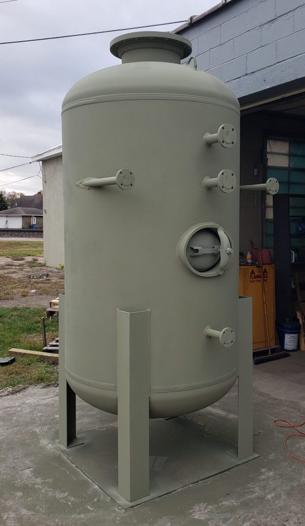
- For a Blowdown Tank – after the flash steam is vented, these units use natural convection over a 6-12 hour period to allow the intermittent bottom boiler blowdown to cool. When the next intermittent bottom blowdown is released from the boiler to the tank, that hot blowdown mixes with the previous blowdown water. This previous blowdown water we are referring to is the remaining blowdown water that did not reach the level of the over flow drain on the tank. Since this previous blowdown water has now cooled over a 6-12 hour window, it is able to immediately quench the entering hot blowdown water, resulting in a mixed temperature of ≤ 140°F. The blowdown tank’s water level then rises up to, and out of the overflow drain. This processes is repeated every 6-12 hours.
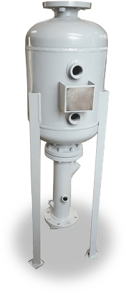
- For Blowdown Separators – these units are usually equipped with an Aftercooler Kit. After the steam is vented, the remaining hot water is drained through the aftercooler which uses cooling water to immediately quench the hot boiler blowdown to a safe temperature. A baffle is placed inside the aftercooler to assist the mixing of the two liquids. (Cooling water is not recoverable for purposes of using it again as boiler feed water. The cooling water quenches and is drained with the hot boiler blowdown water.)
- Q: So is that the only difference? How they cool the boiler’s dirty blowdown water?
- To put it simply, yes, that is the only core difference; however a couple other things stand out as a result of how these units cool the blowdown. A blowdown separator is designed to be much more compact since it does not need to contain the blowdown for an extended amount of time. Because it can be equipped with an aftercooler and the aftercooler immediately disposes of the hot blowdown, it takes up less floor space and typically has a lower cost than most of our blowdown tanks.
- Q: Can you customize these units at all?
- We certainly can. Take this as an example, Madden blowdown separators are designed to handle blowdown from boilers operating up to 300 psi, so let’s say your boiler(s) operates above 300 psi, we can design a blowdown tank to handle the increase in pressure; and on top of that, if waiting 6-12 hours for the remaining hot blowdown is not ideal, we can also design and equip an aftercooler to a blowdown tank’s drain to allow immediate disposal.
Do you prefer to be able to see the blowdown water level in your tank at any time? We can add a sight glass to it. Always feel free to reach out with your specifications, Madden is here to help design the best tank/separator for your application.
Call (574) 295-4292 or email: info@maddenep.com
New Product Development
Over the past several months, Madden has received inquiries needing cost friendly, smaller blowdown or blowoff tanks, and we responded. We have designed 3 more, cost effective boiler blowdown tanks to add to the blowdown tank family. Check them out in our charts (BD1600, BD2400, BD3000).
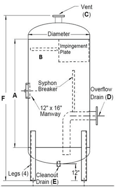
| Model Number | Diameter | Shell A | NPT B | 150#RF C | Flange D | NPT E | OAH F |
|---|---|---|---|---|---|---|---|
| BD1600 | 16” | 35.5” | Up to 2” | *2-1/2” | *2” | 2” | 66” |
| BD2400 | 24” | 32” | Up to 2” | *3” | *2” | 2” | 66” |
| BD3000 | 30” | 29” | Up to 2” | 4” | *2” | 2” | 66” |
| BD3600 | 36” | 30” | Up to 2” | 4” | 3” | 2” | 70” |
| BD4200 | 42” | 42” | Up to 2” | 5” | 3” | 2” | 85” |
| BD4800 | 48” | 48” | Up to 2” | 6” | 4” | 2” | 94” |
| BD5400 | 54” | 66” | Up to 2” | 6” | 4” | 2” | 116” |
| BD6000 | 60” | 72” | Up to 2” | 6” | 4” | 2” | 125” |
| BD7200 | 72” | 96” | Up to 2” | 10” | 4” | 2” | 155” |
- Shell length (Dimension A) and connections size dimensions can be changed to meet the application requirements for the specific boiler as determined by design rule calculations.
- Sizing of tank and connections should be determined using National Board design rules for blowoff tanks.
- Contact the factory for assistance.
- Construction: ASME Section VIII, Div. 1, 50 psi DWP, with National Board serial number
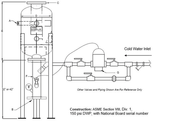
| Blowdown Separator Model # | Blowdown Inlet -A- | Drain -B- | Vent -C- | Vessel Diameter -D- x Height -E- | Aftercooler Part No. -F- | Cold Water Inlet Size | Aftercooler Size | Regulating Valve Number | Valve Size -G- |
|---|---|---|---|---|---|---|---|---|---|
| Boilers Up To 150 psi. | |||||||||
| BD130A22 | 3/4” | 2-1/2” | 2-1/2” | 10” x 30” | AC200 | 3/4” | 2-1/2” | AC102 | 3/4” |
| BD130B23 | 1” | 2-1/2” | 3” | 10” x 30” | AC200 | 3/4” | 2-1/2” | AC102 | 3/4” |
| BD130C44 | 1-1/4” | 4” | 4” | 16” x 30” | AC400 | 1-1/4” | 4” | AC104 | 1-1/4” |
| BD130D45 | 1-1/2” | 4” | 5” | 16” x 30” | AC400 | 1-1/4” | 4” | AC104 | 1-1/4” |
| BD130E55 | 2” | 5” | 5” | 16” x 30” | AC500 | 1-1/2” | 5” | AC105 | 1-1/2” |
| Boilers Up to 300 psi. | |||||||||
| BD242A34 | 3/4” | 3” | 4” | 16” x 42” | AC300 | 1” | 3” | AC103 | 1” |
| BD242B44 | 1” | 4” | 4” | 16” x 42” | AC400 | 1-1/4” | 4” | AC104 | 1-1/4” |
| BD242C45 | 1-1/4” | 4” | 5” | 16” x 42” | AC400 | 1-1/4” | 4” | AC104 | 1-1/4” |
| BD242D56 | 1-1/2” | 5” | 6” | 16” x 42” | AC500 | 1-1/2” | 5” | AC105 | 1-1/2” |
| BD242E68 | 2” | 6” | 8” | 16” x 42” | AC600 | 1-1/2” | 6” | AC105 | 1-1/2” |